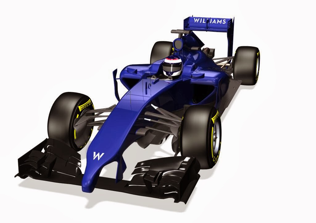
Front Wing
The Front Wing presented on the render is the same one utilised by the team late on last season bar the reduction of 75mm either side to fall inline with the new regulations.
The 6/7 tier designs we saw used by the teams in the last few seasons will continue as they all look for efficiency over a wider spectrum to which this image attests to. The use of the outer 'r' Cascade which integrates a flapped/winged section helps to airflow around the upper, outer quadrant on the front
tyre. This is aided by the use of the much larger multi element / serrated Cascade outbound of it which bleeds pressure off during Yaw.
As I've talked about here on the blog before, the multiple/split flap arrangement seen in these images is not only conducive to create front end downforce but also helps to create a deeply entwined Vortex along the Y250 region.
The nose as we know has once again become an area of scrutiny for 2014 with the FIA's wording allowing for what many have described as a male appendage. Just like the debacle that surrounded 2012's challengers, the wording of the regulations afforded the teams a way in which to retain the height at the rear of the nose. This allows more airflow under the chassis and minimizes some of the losses that would have occurred otherwise. The design shown here is likely to change throughout testing and the early part of the season as the team find additional gains by pushing the crash structure element to it's limits. The sharply inclining stub section at the fore of the nose is shaped with a gentle inward curve to further increase the space behind it. Meanwhile the connecting Nose/Wing pylons have been shaped to create a flow conditioning effect that can be utilised further downstream. Although they look like a two part design the angle of the image is deceptive and the pylons simply arc inward (Regulations only permit a singular section in this region). Underneath the chassis we find a fairly simple set of Turning Vanes which are again most likely a placeholder for the render.
Cooling is one of the essential parameters for 2014 with the Intercooler likely placed in one Sidepod, whilst the other takes care of the regular engine radiator. The Inlet shown here fits a similar profile to that used on the FW35 along with an identical Airflow Conditioner to that used at the end of last season. No Vortex Generators adorn the top of the Sidepod but as this is just a render that is likely to change too.
As we can see here from the side on view made available by the teams twitter feed the splitter region of the car is taken up by a section of wedged chassis above which helps to divert the airflow around the front of the Sidepods. What is interesting though is this section extends forward to meet with the bulkhead at a narrower width than the chassis above it.
The roll hoops construction spars are seemingly very narrow but where most teams usually only utilise either a much thicker central spar or 2 thicker outer spars, Williams seem to have adopted 3 much narrower spars. Due to the image being of low resolution it's difficult to get a good shot but if you notice in the circled section the team have placed a selection of Louvres which are likely in place to relieve heat from the surrounding area.
The side view of the car shows us that the team are looking at the possibility of splitting the lower portion of the airflow conditioner. The Sidepod itself is very much like the design seen yesterday from Force India with a decent undercut at the front of the Sidepod (under the inlet) allowing airflow around the lower region and across the floor. Meanwhile a large exit is made at the rear of the Sidepod to allow the waste airflow used by the intercooler/radiators to be dispatched of. As we can see the team has also decided to retain their approach to the the engine cover with a short cover meeting the dimensional regulations with the aid of Shark Fin. The side view also affords us the chance to see that Williams will take the opportunity to integrate the exhaust pipework within a shroud attached to the gearbox/crash structure casing.
The rearward shot also confirms that the exhaust tip points upwards from the gearbox/crash structure point of origin. This image however gives us a clear indication that the team are looking to place a Monkey Seat in the Y100 zone behind the exhaust outlet. It also shows the teams intention to run without the supporting pylons and will instead create rigidity for the rear wing structure by affixing the wing to the floor/diffuser.
The rear floor of the car indicates that the team will run with tyre squirt slots ahead of the rear tyre, whilst an erant piece of floor seems to be targeting (perhaps a vortex) at the gap between the tyre and the diffusers edge.
Lastly the team are seemingly retaining their tyre wake slots in the leading edge of the rear wings endplates.
This article will be updated when fresh images are made available


